
General introduction
Structural integrity is the ability of a structure to withstand its intended loading without failing due to fracture, deformation, or fatigue. It is a concept often used in engineering to produce items that will serve their designed purposes and remain functional for a desired service life.
ACI 318 – 19 defines structural integrity as the “ability of a structure through strength, redundancy, ductility, and detailing of reinforcement to redistribute stresses and maintain overall stability if localized damage or significant over stress occurs.” In all cases integrity is a minimum check, always superseded by demand.
The current ACI 318 – 19 further explicitly includes a requirement of integrity defined in Chapter 7 for one-way slabs, in Chapter 8 for two-way slab systems, and in Chapter 9 for beams.
Structural integrity has previously, partially explicitly and mostly implicitly been our structural codes for some time. In the ACI 318–14, the reformatted code, two-way slabs first appeared explicitly along with beams that previously were included explicitly and one-way slab were explicitly included in the 318-19 version. In the older code (i. e. ACI 318–11 and some previous), older format explicitly deals with integrity in section 7.13 reinforcement for structural integrity and is primarily for beams. All other issues of integrity are mostly in the commentary.
Summary of Integrity Rebar Requirement non-PT Sections (pour strips)
These following requirements are a minimum check for low moment areas. Greater moment demand will always govern.
One-Way Slabs
Integrity reinforcement consisting of at least 1/4 of the maximum positive moment reinforcement shall be continuous.
Two-Way Slabs
Integrity reinforcement consisting of at least the greater of As=4.5 √f’c c2 d / fy or As=300 c2 d / fy shall be continuous. For an 8-inch slab, 5000 psi concrete, grade 60,000 psi steel is less than 1 square inch of rebar.
Beams
Integrity reinforcement consisting of at least 1/4 of the maximum positive moment reinforcement (bottom) shall be continuous and at least 1/6 of the maximum negative moment reinforcement (top) shall be continuous.
Integrity in the ACI 318 – 19 code
Integrity first appears in Chapter 2 Notation and Terminology, 2.3 Terminologies, then next in Chapter 4 Structural System Requirements, 4.10 Structural integrity and in Table 4.10.2.1 describes minimum requirements for structural integrity.
Integrity is explicitly defined starting with slab elements in Chapter 7, One-Way Slabs, Chapter 8, Two-Way Slabs and Chapter 9 Beams.
Slabs
One-Way Slabs
Section 7.7.7 Structural integrity reinforcement in cast-in-place one-way slabs, explicitly defines the requirement for one-way slabs.
7.7.7.1 longitudinal structural integrity reinforcement consisting of at least one-quarter of the maximum positive moment reinforcement shall be continuous. The commentary further states that one-way slabs integrity should be similar to that of beams.
Two-Way Slabs
In Chapter 8 two-way slabs, section 8.7.5.6 Structural integrity explicitly defines structurally integrity requirement for two-way slabs.
8.7.5.6.1 Except as permitted in 8.7.5.6.3 at least two tendons with ½ in. diameter or larger strand shall be placed in each direction at columns in accordance with (a) or (b): which further define the tendon requirement for integrity.
8.7.5.6.3 Slabs with tendons not satisfying 8.7.5.6.1 shall be permitted if bonded bottom deformed reinforcement bars provided each direction in accordance with 8.7.5.6.3.1 through 8.7.5.6.3.3 which further define explicitly the integrity requirement for reinforcement bars.
- 8.7.5.6.3a As=4.5 √f’c c2 d / fy
- 8.7.5.6.3b As=300 c2 d / fy
All the terms are in ACI 318-19 and familiar except maybe c2 , which is the width of the column in the direction being considered.
Beams
Section 9.7.7 Structural integrity reinforcement in cast-in-place beams defines the integrity requirement for beams. There are a number of requirements but one-quarter of the maximum positive moment but not less than two bars or strands shall be continuous and at least one-sixth of the negative moment reinforcement at the support but not less than two bars or two strands shall be continuous.
Further in section 9.8.1.6 For structural integrity of joist at least one bottom bar in each joist shall be continuous and shall be anchored to develop fy at the face of the supports.
Potential violation of structural integrity in R/C or post tension structural concrete
Typically for cast-in-place concrete structures either reinforced with mild steel or reinforced with post-tensioned steel, the integrity issue is often a non-issue. This is because the normal flexural steel reinforcing is continuous through the points of inflection everywhere, for uniform loads, mostly far exceeding the lesser integrity requirement. Furthermore, with post-tensioned slabs the post-tensioning is always continuous from anchor to anchor and combined with the mild steel reinforcing, which is required to exceed the flexural demand.
This previous discussion also applies to joints and the traditional pour strip, where the post-tensioning is interrupted, as now this portion of the slab is mild steel reinforced.
The exception may potentially be the gapless pour strip. Currently, to this author’s knowledge, there are two versions of a gapless pour strip, (1) the slab shear connector, and (2) PS=Ø® Steel Reinforcement Splice System. These will be fully discussed.
Traditional/Conventional pour strip with gap and structural integrity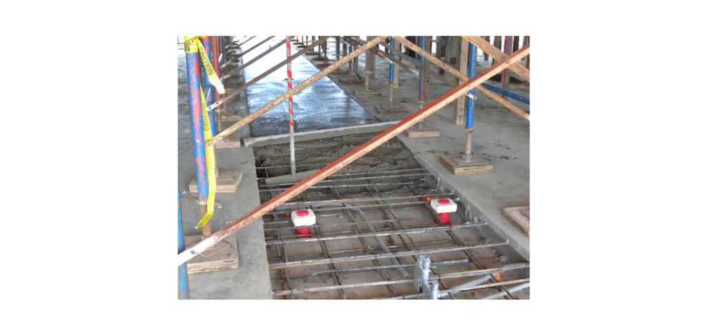
Figure 1 Traditional Pour Strip with lapping rebar
General
The traditional/conventional pour strip allows for slab volume change and on completion connects the reinforcing steel utilizing a lap splice. Further, the diaphragm chord steel, which is ACI permitted, is also lap spliced. Thus, the traditional/conventional pour strip provides all ACI required reinforcement including continuity and integrity with a gapped pour strip. The system has and continues to perform successfully but reduces productivity, while open, and often is closed too quickly by construction schedule of other trades. This further reduces quality by causing additional shrinkage cracking. This solution has always set quality against schedule (i.e. cannot get both), with the EOR in the middle.
Gravity loads: Locations
Mid span
At this location the moment, for a uniform load, is at its maximum, the integrity check at this location is obviously a non-issue. This is due to the integrity rebar requirement, being only one-quarter of the maximum positive moment, which is required to exceed the maximum moment demand. Splicing is a lap splice.
One-fifth span
In the case of either one-way or two-way slabs, at this location the moment, for a uniform load, is at its minimum, the integrity check here is important and likely to govern the amount of rebar required at this location.
Since there often is no post-tensioning steel in the pour strip, this portion of the slab is a mild steel reinforced concrete slab and all the moment tension resistance will be mild steel rebar.
For the one-way slab, the integrity rebar required must provide one-quarter of the maximum positive moment in the span.
For the two-way slab, the integrity rebar area required must provide an area greater in area calculated by the equation 8.7.5.6.3.1 (a) or 8.7.5.6.3.1 (b). Further, for two-way slabs the rebar maximum strength is limited to 80,000 psi.
The important thing here is that in either case or location of the pour strip there is reinforcement that must be continuous connecting two pieces of slab together structurally, as the traditional/conventional pour strip does. If the integrity/continuity requirements are not met the joint is not part of a slab continuation but simply an expansion joint. The lateral system then must be designed based on type of the joint either with integrity/continuation or without.
Lateral loads: Diaphragms
The diaphragm is not direct integrity but is usually a part of the conventional/traditional pour strip, which needs to be connected for the lateral system to work properly. Ductility cannot be achieved with a short local tension device but must connect rebar with one of the three (3) code permitted methods.
For lateral loads, the slab acts as a horizontal beam transferring lateral loads (i.e. wind and seismic) to the lateral resisting elements typically braced frames, moment frames or shear walls.
Shear resistance:
With regard to the traditional pour strip this lateral shear resistance is provided either by shear keys in the slab and/or shear friction created by the reinforcement passing through the joint after the PS=0 is grouted. The normally provided reinforcing steel is usually sufficient but should be checked.
Moment resistance:
Again for the traditional pour strip, this element is often referred to as the chord steel which is the reinforcing bars near the edge of the slab along the longitudinal sides of the slab.
Since ACI 318–14 and including ACI 318–19, this code has explicitly (i.e. ACI 318-19 Section 12.5.2.3) defined the methods permitted to resist diaphragm tension due to moment by one of four methods:
a) deformed bars conforming to 20.2.1 (i.e. this includes the permitted mechanical splice method)
b) strands or bars conforming to 20.3.1 either prestressed or non-prestressed
c) mechanical connectors crossing joints between precast elements
d) pre-compression from prestressed reinforcement
These explicitly are the only permitted methods to resist tension moment in diaphragms.
The slab, together with the chord steel reinforcement, achieves all the requirements of ACI 318 for flexure and shear and meets the integrity requirements, while minimizing restrain to shrinkage cracking. The traditional gapped pour strip for decades has successfully provided the intent of the ACI code and increased quality by reducing cracking.
We do know that shrinkage is the major factor in concrete volume change. Further, at 28 days a little over 40% of the shrinkage has occurred and at 60 days a little over 40% remains. At 120 days about 30% of the shrinkage remain. It is clear to see that better quality with less cracking is achieved the longer the joint is open/.
In the following discussion of more recent gapless pour strips, we will review how these compare to the traditional pour strip, while speeding up the construction schedule, providing better safety and providing relief for restraint of shrinkage/volume change in the concrete structure.
Gapless pour strips and structural integrity
The next sections will discuss how some of these gapless pour strips may violate these previously discussed code provisions and requirements for integrity. Most engineers agree for the need to provide for relief of restraint to shrinkage cracking. Further, we all know the schedule and safety challenges associated with the traditional gapped pour strip and its gap. A gapless solution to comply with ACI code like the traditional pour strip and done properly may be allowed to remain open for a much longer time, further improving the quality of the concrete structure by allowing more time for the shrinkage/volume change to occur before locking the reinforcement.
Embedded Release Devices:
Slab Shear Connector:
General:
The slab shear connector is a shear device that has been around for a few decades. Most engineers will treat this joint created by the slab shear connector as an expansion joint.
Based on the slab shear connector available data tables most of these values seem to far exceed values that would be calculated in ACI 318 – 19 Chapter 17 for shear or tension. Again the ACI 318 values can easily be calculated by the EOR. The difference might be attributed to selection of safety factor by the manufacture.
The slab shear connector normally is located at a fifth span (i.e. zero moment area for uniform loads) it would be more appropriate for the engineer to use the ACI calculated values if this device is being used.
Regarding the tension aspect of the diaphragm chord streel, Chapter 12 in ACI 318-19 is clear as to what is permitted in ACI code for the tension of the lateral load resisted by the diaphragm.
Gravity loads: Locations
Mid span
It is possible that this location could be a short span with a post tension slab fully supporting all loads. In this case in the area between post tension anchors the slab is unreinforced the code would require a minimum of temperature/shrinkage steel reinforcing. Elevated slabs are not permitted to be unreinforced (i.e. plane) concrete. This is more like anchor bolts or expansion bolts providing integrity, a non-ductile mechanism subject to the breakout calculations of ACI 318 Chapter 17.
One-fifth Span
This is the most typical location for the slab dowel as the flexural requirement is low for a uniform load. In this case the integrity requirements of both Chapter 7 for one-way slabs and Chapter 8 for two-way slabs require a prescribed amount of reinforcing steel to connect the concrete slabs in their final condition. As stated in ACI 318 this integrity steel reinforcement is required for ductility.
The connection provided by the slab shear connector, is through a group of U-shaped rebar. This is not a ductile connection but a brittle breakout type connection/pull out. If there is a moment capacity it is very local and could not be an equivalent to the integrity requirements of Chapter 7 or Chapter 8.
Lateral loads: Diaphragms
Diaphragm moment-tension resistance is explicit in ACI 318-19 Chapter 12 as to what is permitted for the tension/diaphragm chord. This certainly is due to the fact that it is not a ductile mechanism but a very brittle non-ductile type of failure mechanism.
The slab shear connector system provides for the reaction of the four-fifths span on to the one-fifth span. This is effectively a pin connection. During construction this does allow for reshoring the slabs, if they are self-supporting. But it does not in the final condition, provide for any integrity steel required by ACI 318. This is effectively an expansion joint and must be treated as such for the design of the entire lateral system.
PTI DC20.2-22 recently published includes an embedded release device, albeit old technology, as it seems difficult for many organizations to keep up with emerging technology. The document can be purchased on the PTI website. https://www.post-tensioning.org/
PS=Ø® Steel Reinforcement Splice System an Embedded Release Device
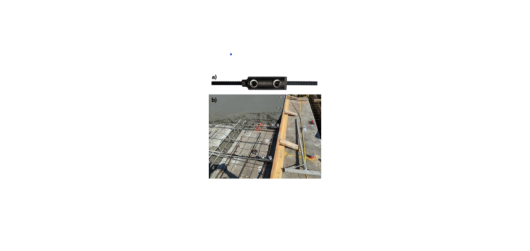
Figure 3 The PS=Ø® Coupler and Installation
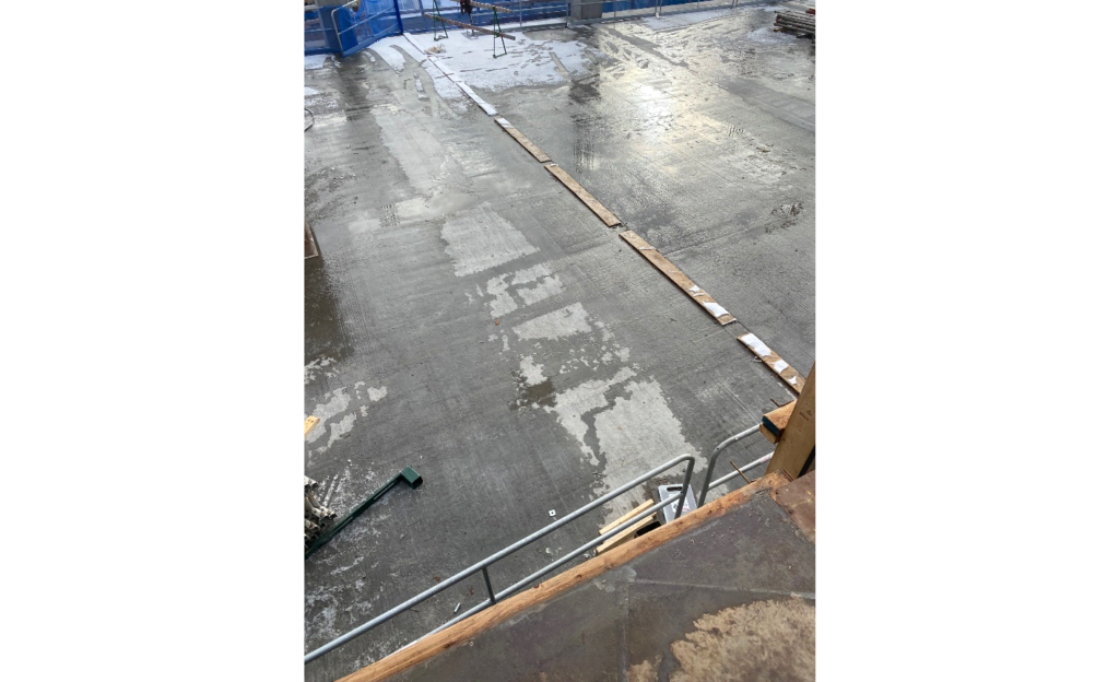
Figure 4 The PS=Ø® Joint top and bottom
General
PS=Ø® Steel Reinforcement Splice System allows for slab volume change and on completion connects the reinforcing steel (i.e. slab flexure and diaphragm chord). The technical difference is how the rebar are connected, mechanical splice for PS=Ø® joint and lap splice for the conventional/traditional pour strip both permitted by ACI. Thus, the PS=Ø® joint provides total continuity and integrity with a gapless pour strip. This system is functionally identical to the conventional/traditional pour strip without the gap.
Gravity loads: location
Mid span
Again at this location the moment, for a uniform load, is a maximum. This is a common location particularly in post tension slabs where each of the cantilever’s half slabs can be made to be self-supporting, so less expensive reshoring can be used.
In this location the PS=Ø® Steel Reinforcement Splice System acts as a continuation of the flexural rebar in tension to resist the moment. Typically the amount of moment needed to resist is a part of the dead load and all of the live load since much of the self-load is self-supporting through the post tensioning, the amount of rebar is more than adequate to provide the integrity steel required in Chapter 7 for one-way slabs and Chapter 8 for two-way slabs. Further, in mild steel slabs (i.e. non post tension) rarely can these cantilevers be self-supporting and that requires more expensive backshoring.
One-fifth span
This is often the location of choice by the engineer of record (EOR). The reason for the choice of course is a small moment demand at this location. In the case of the traditional/conventional pour strip the more expensive back-shoring is required.
Using the PS=Ø® Steel Reinforcement Splice System at this location can also eliminate backshoring and typical reshoring can be used much like in the case of the lockable dowel. This location further reduces the amount of post tensioning compared to a self-supporting mid span location.
The PS=Ø® Steel Reinforcement Splice System can temporarily provide support for the four-fifth span while ungrouted, allowing for slab shrinkage to occur. The number of couplers at this location to provide for this temporary condition can easily be calculated using ACI 318-19 Chapter 17. Further, the integrity should be checked to ensure this requirement is also met.
Further, this author has found using the dowel action of the PS=Ø® Steel Reinforcement Splice System that after grouting this number of couplers complies with the integrity requirements of both Chapter 7 and Chapter 8.
The PS=Ø® Steel Reinforcement Splice System also provides a permitted chord steel reinforcement.
Lateral loads: Diaphragms
Diaphragm tension resistance is explicit in ACI 318-19 Chapter 12 what is permitted for the tension as the diaphragm chord. The lockable dowel is not a permitted method. This certainly is due to the fact that it is not a ductile mechanism but a very brittle non-ductile type of failure mechanism.
The engineering functionally is identical to the traditional/conventional pour strip which uses the ACI permitted lap splice. Whereas the PS=Ø® Steel Reinforcement Splice System uses the ACI permitted mechanical splice.
Summary/Conclusion
Comparison of the “Traditional Pour Strip” to the Gapless Pour Strips
| Location of Joint | Moment/Shear | Traditional | Slab Shear Connector | PS=Ø® |
| One-fifth Span | Moment | Yes | No | Yes |
| Shear | Yes | Yes | Yes | |
| Mid Span | Moment | Yes | No | Yes |
| Shear | Yes | Yes | Yes | |
| Diaphragm | Moment | Yes | No | Yes |
| Shear | Yes | Yes | Yes | |
| Integrity | Yes | No | Yes |
The traditional pour strip has been around for many decades and served the concrete industry well in providing better quality product with ductility and less cracking. Its only shortcoming has been the gap that has been economically costly and hindered schedules. The slab dowel has been around for a few decades and clearly from the table does not duplicate the successful traditional pour strip. The PS=Ø® also has its history in mechanical rebar splicing systems that have also been around for 6 decades and recently improved technology to accommodate the volume change in cast-in-place concrete. Now the gapless pour strip may be left open even longer to further produce more crack free concrete construction without interrupting or interfering with the construction schedule.
