
PS=Ø® 101: Everything You Need to Know About Pour Strip Zero
Part 2 – Eliminating Wall Leave-Outs
This is Part 2 of our four-part blog series about PS=Ø®. In Part 1, we focused on the function of pour strips, how to eliminate them with PS=Ø®, concrete volume change, and restraint to shortening (RTS). In Part 2, we will discuss how PS=Ø® eliminates wall leave-outs.
Recap: What is PS=Ø®?
PS=Ø® stands for pour strip zero and is a mechanical reinforcing splice system that eliminates pour strips, wall leave-outs, and expansion joints while maintaining structural integrity and allowing for volume change. It utilizes proven coupler technologies recognized worldwide, featuring a thread on one end and a grout-filled sleeve on the other. The system is an ACI 318 code compliant full-tension mechanical Type 1 and Type 2 rebar splice, is ICC approved, and is made in the USA.
Why Wall Leave-Outs?
Much like pour strips, wall leave-outs solve restraint problems, create rebar continuity, and facilitate load transfer. But instead of joining two concrete slabs, wall leave-outs are used to connect slabs to shear walls. Shear walls are stiff elements that provide lateral stability for a structure. When connecting a shear wall to a slab, engineers will often use a wall leave-out in the slab to allow it to move freely without restraint.
While wall leave-outs offer the same benefits as pour strips, they also cause similar problems. Leave-outs are poured back after the Engineer of Record’s (EOR) specified time, a minimum of 28-days, but are often left open much longer. Although wall leave-outs are great for slab quality, they add a significant amount of time, cost, and safety issues to projects.
The good news is that just as our PS=Ø® system eliminates the need for pour strips, it also replaces wall leave-outs. This reduces cost, accelerates construction, while improving the overall safety of the jobsite.
The Slotted PS=Ø® Coupler
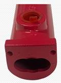
Figure 1. The PS=Ø® Slotted Coupler.
For wall applications, the PS=Ø® system uses a horizontal slotted coupler. This coupler is slightly different in design from the coupler used for traditional pour strips, because it must allow for additional movement.
Pour strips typically only need to account for movement in one direction, longitudinal (or along the length of a PS=Ø® coupler). Walls, on the other hand, always need to accommodate both longitudinal and transverse movement. This is because slabs undergo volume change in two directions, and will shorten by pulling away from and across the surface of a wall. When connected to shear walls, proper release of RTS needs to accommodate both movements.
To allow for these movements, a horizontal slotted PS=Ø® coupler (Figure 1) is used. The horizontal slot allows the rebar in the coupler to move freely in both the longitudinal and transverse directions, fully releasing the slab from the wall.
There are a total of 5 applications in which the PS=Ø® system can be used to eliminate wall leave-outs:
1. Slab to Wall Application
In this application (Figure 2), the wall is typically poured first with either a bent bar or a form-saver bar coming out of the wall. A slotted PS=Ø® coupler is placed onto the bar, and then the slab is poured.
Figure 2. Slab to Wall Application.
2. Slab to Wall With a Temporary Stressing Strip Application
If post-tensioned (PT) tendon stressing needs to take place at the wall, then a temporary stressing strip can be used. This is commonly utilized in subterranean conditions where it is difficult to stress. In this application (Figure 3), the wall is typically poured first, then the first pour takes place. Once the PT is stressed, the second pour can be placed immediately.
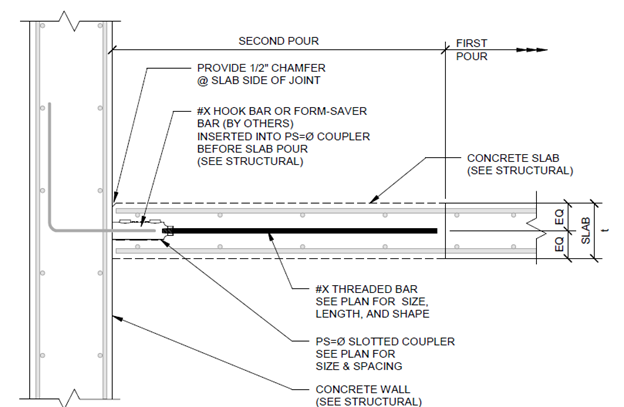
Figure 3. Slab to Wall with a Temporary Stressing Strip Application.
3. Slab to Top of Wall Application
This application is very similar to the slab to wall application, except that the top of the wall is notched to allow the slab to receive a horizontal bar coming out of the wall.
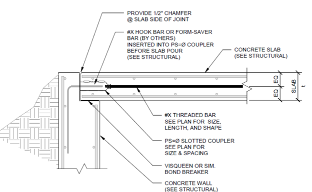
Figure 4. Slab to Top of Wall Application.
4. Slab to Top of Wall with a Temporary Stressing Strip Application
If PT stressing needs to take place at the top wall, then a temporary stressing strip can be used. In this application (Figure 5), the first pour takes place before the PT is stressed. After PT stressing, the second pour can be placed immediately.
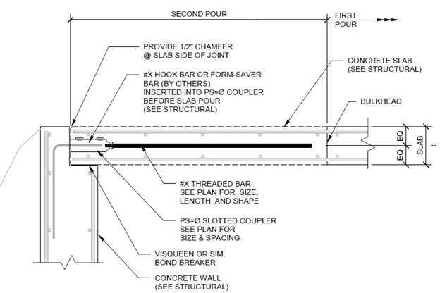
Figure 5. Slab to Top of Wall with a Temporary Stressing Strip Application.
5. Slab Over Top of Wall Application
In this application (Figure 6), the slab is poured over the top of the wall and a multi-directional PS=Ø® coupler is used vertically in the wall. This coupler has a large circular hole that allows the slab to move freely in any direction.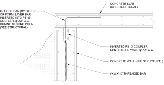
Figure 6. Slab Over Top of Wall Application.
