
PS=Ø® 101: Everything You Need to Know About Pour Strip Zero
Part 4 – Installing PS=Ø®
This is Part 4 of our four-part blog series about the PS=Ø® system, where we discuss the installation process. In Part 1, we focused on the function of pour strips and how to eliminate them with PS=Ø®. In Part 2, we reviewed how PS=Ø® eliminates wall leave-outs and in Part 3, we demonstrated how PS=Ø® can be used to eliminate expansion joints.
In the fourth and final part of this blog series, we will explain the installation process of PS=Ø® as it pertains to the:
- Slab to Slab Application
- Slab to Slab with a Temporary Stressing Strip Application
- Slab to Wall Application
- Expansion Joint Application
Recap: What is PS=Ø®
PS=Ø® stands for Pour Strip Zero, and is a mechanical reinforcing splice system that eliminates pour strips, wall leave-outs, and expansion joints while maintaining structural integrity and allowing for volume change. It utilizes proven coupler technologies recognized worldwide, featuring a thread on one end and a grout-filled sleeve on the other. The system is an ACI 318 code compliant full-tension mechanical Type 1 and Type 2 rebar splice, is ICC approved, and is made in the USA.
What You Get With PS=Ø®
When you purchase the PS=Ø® system, you’ll have all the tools and accessories needed for a complete installation, from start to finish. We also offer comprehensive, virtual and in-person support on the jobsite to ensure the installation process goes smoothly.
Below is a complete list of the tools and accessories you will receive to assist you in the installation process:
Full Package:
- PS=Ø® couplers
- Torque wrench
- Threaded grout tubes with caps
- Bond breaker and sprayer
- Non-shrink grout
- Grout mixing tool
- Slump-measuring tool
- Grout funnel
Full Support:
- Technical support
- Shop drawings
- On-site assistance from PS=Ø® personnel
1. Slab To Slab Installation
In this section, we will review the 11 steps to install the PS=Ø® system in a slab to slab application. We will also refer back to this section to clarify and define the installation processes for subsequent applications.
Pre-Installation Meeting: Before each installation, we hold a virtual pre-installation meeting with each of our customers. During this meeting, we review the installation process with you and go over your project in detail so you know what to expect.
On-Site Assistance: The system is simple to install, however, we send a PS=Ø® representative to be there with you on site during your first installation.
The 11 steps for basic PS=Ø® installation are as follows:
The PS=Ø® coupler can be placed in the first or second pour, but it is easiest to fasten it to the bulkhead in the first pour (Figure 1). If the coupler is placed in the second pour, rebar must stick out of the first pour so the coupler can be placed on it prior to the second pour; this is the typical process for wall applications where the wall is often placed prior to the slab.
PS=Ø® Relief Joints are typically located at the inflection point (closer to columns, i.e. not mid-span) between columns with the coupler placed at mid-depth of the slab. If the slabs are designed appropriately, at this location the PS=Ø® system creates self-supporting slabs and no backshoring is required.
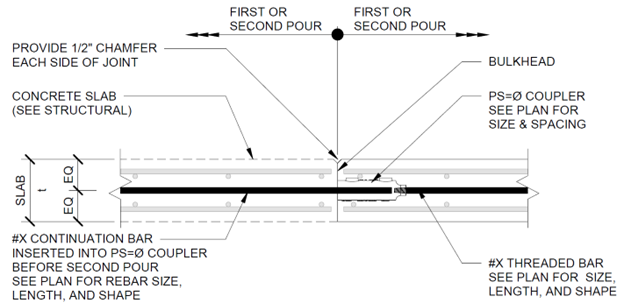
Figure 1: Typical Slab to Slab Detail
Installing the PS=Ø®:
Step 1: Torque Threaded Rebar
Remove thread protector and torque threaded rebar into coupler using the torque wrench. We recommend using a tripod pipe chain vise (Figure 2).
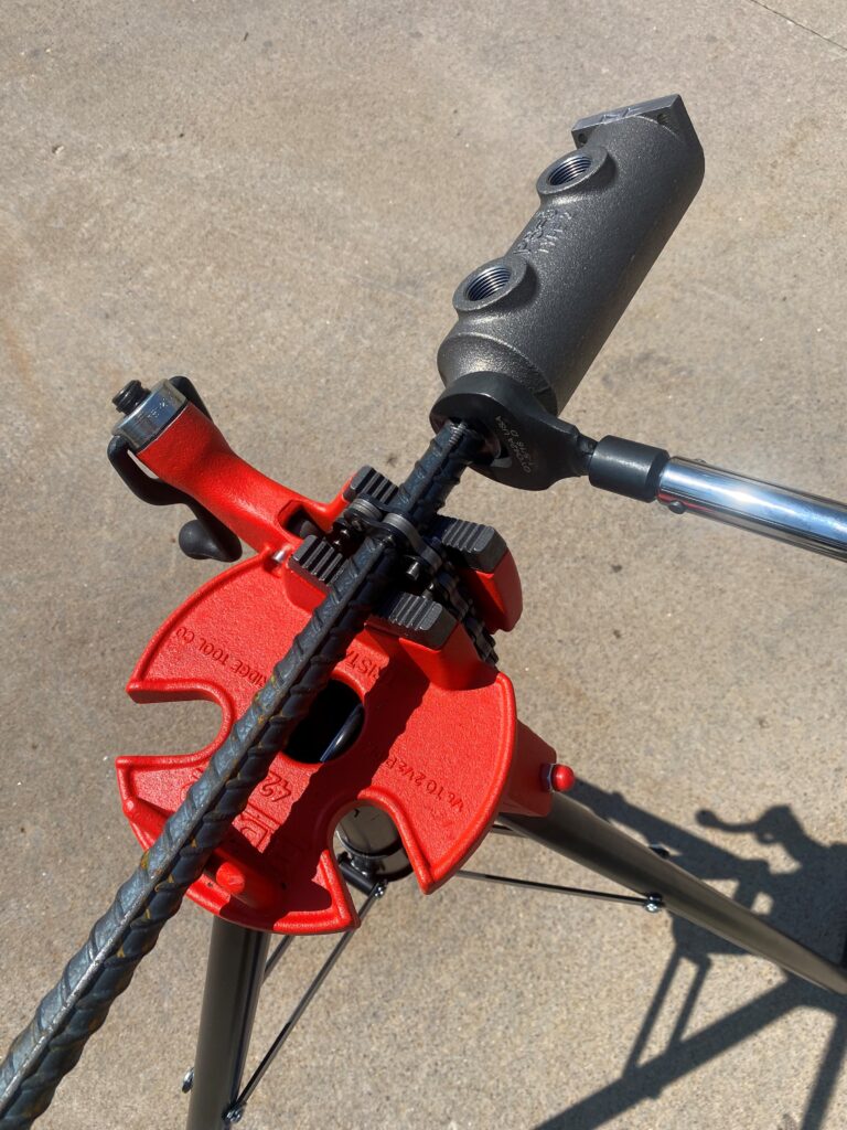
Figure 2: Torquing Threaded Rebar into a PS=Ø® Coupler
Step 2: Thread In Grout Tubes
Thread grout tubes with caps into coupler. This can be done prior to fastening the assembly to the bulkhead or after. It is typically preferred to cut the grout tubes to slab height, which makes finishing the concrete easier.
Step 3: Fasten Coupler Assembly To Bulkhead
Fasten the coupler to the bulkhead (Figure 3). Couplers are most often placed in the mid-depth of slabs. In post-tensioning (PT) slabs with a bottom and top mat, place the bottom mat first, then the PS=Ø® system, then the PT tendons, and then the top mat.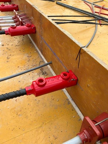
Figure 3: PS=Ø® Couplers Fastened to Bulkhead
Step 4: Pour First Pour Concrete
In PT slabs, tendons are stressed from either slab edge after the first pour, and can be stressed from both ends if needed.
Step 5: Insert Continuation Rebar
Fully insert the continuation rebar into the coupler.
Step 6: Apply Bond Breaker
Spray the bond breaker on the first pour slab edge.
Step 7: Pour Second Pour Concrete
In PT slabs, tendons are stressed from the opposite slab edge of the PS=Ø® Relief Joint.
Step 8: Pull Formwork and Reshore
After the second pour, the system will typically be self-supporting, all of the formwork can be removed and reshores placed. Reshores can be removed at the same time as other reshores, i.e. reshores do not need to stay in place until couplers are grouted.
Grouting the Coupler and Joint:
During the time specified by the engineer of record (EOR) the PS=Ø® Relief Joint will open up, as the concrete shrinks, creating a small gap between pours. The couplers and joint can be grouted after the specified amount of time, which locks the system in from further movement. There will be fewer restraint cracks and better performance, the longer you leave the system ungrouted.
Step 9: Seal Bottom of Joint
A small gap is created between pours and must be sealed prior to grouting. The most common method of sealing the joint is using a backer rod.
Step 10: Mix Grout
Using the grout mixing tool and slump-measuring tool provided, mix grout to the required consistency and test flowability.
Step 11: Grout Couplers and Joint
Using the grout funnel provided, simply pour grout into the funnel and grout the joint and couplers (Figure 4). When grouting the couplers, the grout tube caps must be removed from both tubes. Then place funnel in one hole and wait until grout comes up from the other hole. Full coupler grouting is achieved when all the air is pushed out of the other hole and grout is seen. Take grout cube test samples for compression testing.
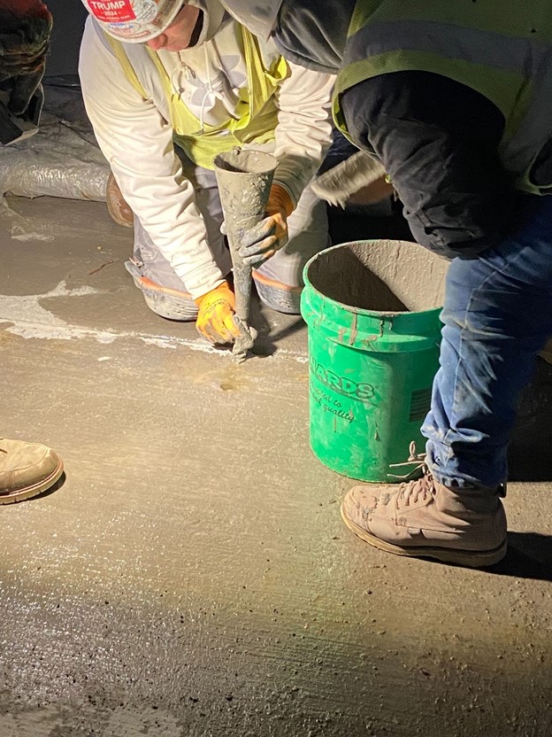
Figure 4: Grouting PS=Ø® Couplers and Joint
2. Slab to Slab with a Temporary Stressing Strip Installation
Recall from Part 1 our slab to slab with a temporary stressing strip application (Figure 5). In this application there is a temporary leave-out (for stressing PT tendons) between the first and second pour. The third pour is placed after stressing the PT tendons.
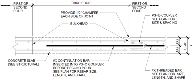
Figure 5: Typical Slab to Slab with a Temporary Stressing Strip Detail
In this application, the PS=خsystem installation is the same for the first pour, except for two extra steps to account for the temporary stressing strip: 1) Stressing the PT tendons, and 2) pouring back the stressing strip.
See below:
Steps 1-4 [From Above]
Step 5: Stress PT Tendons in First Pour
Step 6: Pour Second Pour Concrete
With a temporary leave-out between the first and second pour, this pour is no different than pouring a slab adjacent to a traditional pour strip where the rebar from the second pour extends into the leave-out (Figure 4) but does not cross the PS=Ø® Relief Joint between the first and third pours; the only rebar crossing the joint is the continuation rebar.
Step 7: Stress PT Tendons in Second Pour
This is done from the temporary stressing strip.
Step 8: Insert Continuation Rebar
This rebar can be placed before or after the second pour. Fully insert the continuation rebar into the coupler.
Step 9: Apply Bond Breaker
Spray the bond breaker on the first pour slab edge.
Step 10: Pour Third Pour Concrete
After approval of the PT tendon stressing records the third pour can be placed without delay.
Step 11: Pull Formwork and Reshore
After the third pour, the system will typically be self-supporting, all of the formwork can be removed and reshores placed. Reshores can be removed at the same time as other reshores, i.e. reshores do not need to stay in place until couplers are grouted.
Grouting the Coupler and Joint (see above):
During the time specified by the engineer of record (EOR) the PS=Ø® Relief Joint will open up, as the concrete shrinks, creating a small gap between pours. The couplers and joint can be grouted after the specified amount of time, which locks the system in from further movement. There will be fewer restraint cracks and better performance, the longer you leave the system ungrouted.
3. Wall Application Installation
Recall from Part 2 our various wall applications (Figure 6). In the context of a wall application, PS=Ø® installation process is the same as the typical slab-to-slab installation process, except for a few points regarding the PS=Ø® coupler’s placement:
In general, walls are poured first with a short piece of rebar sticking out of the wall; a form saver with a short piece of rebar screwed can also be used. The PS=Ø® coupler is placed on the rebar sticking out of the wall. Bond breaker is then applied to the wall/slab edge after the coupler has been placed, before the slab is poured.
The grouting process is identical to the typical application.
Slotted Coupler: For wall applications, we always use the slotted PS=خcoupler to allow for both longitudinal and transverse movement.
Note: Wall applications may also include a temporary stressing strip (see above), to allow for PT tendon stressing. After approval of the PT tendon stressing records the stressing strip can be placed without delay.
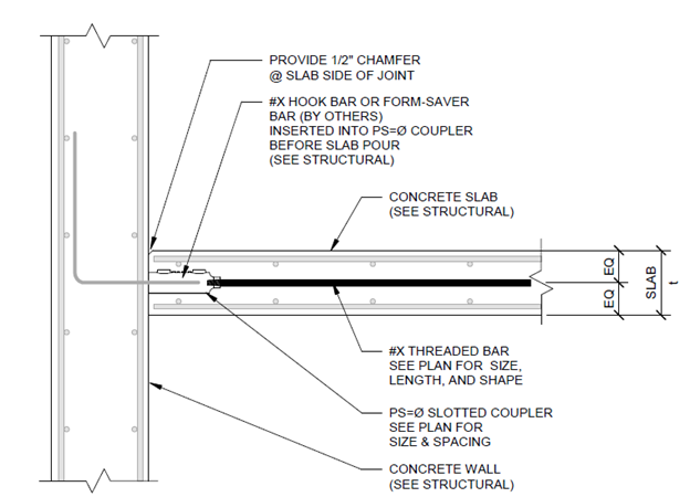
Figure 6: Typical Slab to Wall Detail
4. Expansion Joint Application Installation
Recall from Part 3 our expansion joint applications. When it comes to installing PS=Ø® to eliminate expansion joints, the installation process is the same as the slab-to-slab application, except the grouting process happens much later. The primary function of an expansion joint is to allow for thermal expansion (and contraction) during construction. Once a building is enclosed and under regulated temperature, the need for an expansion joint diminishes, thus couplers and joints are grouted after this takes place.
Considering PS=Ø® for Your Next Project? Contact Us Today!
Are you tired of dealing with the problems of pour stips, wall-leave outs, and expansion joints? Contact us today to schedule a meeting, or call us at (800) 355-8414. We look forward to talking with you about how PS=Ø® can reduce costs, accelerate construction, and improve safety on your next project!
